Thursday, November 20, 2014
Troubleshooting STR IC Regulator Power Supply
- No start-up voltage supply Vcc or a voltage less than 16V
- Electrolityc Capacitors supply voltage Vcc filter dry.
- Electrolityc Capacitors supply voltage Vcc filter on a pin-4 dry. Replace with a value equal to or slightly larger. - triger UVLO
- input filter capacitor on pin-1 feed dry behind the declining value - triger OLP
- Rectifier diode of the switching transformer is damaged (sometimes when examined with avo-meter looks like a still good)
- cause the supply voltage Vcc drops of the switching transformer (UVLO)
- Part damage or broken lines on the feedback circuit of the voltage regulator through B to photocoupler - triger OVP
- Electrolityc Capacitors dry filter voltage B - triger OVP
- One of the output voltage of the switching transformer secondaries there is a short (over load) - triger OLP
- Soft start capacitor value decreases - triger OLP

- Transformer windings slack.
- If there are ceramic capacitors - can sometimes cause interference noise due to its characteristic piezoelectrik like crystal resonator. Replace with film capacitors.
- Sensor OVP small value resistor on pin-2 to the ground so that the value of delayed triger to OLP or OCP.
- Regulator IC is damaged
Sunday, October 26, 2014
IC 741 Simple High Pass Filter
This be Simple high pass Filter perform filter especial tall frequency can change only. By use IC 741 , be the integrated circuit op-amp very the circuit helps to are high frequency Filter model to be simple. By from the circuit will let 750 HZ frequencies s go up change more well , 60HZ frequencies are or lower. By friends can change the value RC for filter the frequency that can want which can see the detail has followed circuit picture yes.
Thursday, October 23, 2014
IC M3481 Music box versatile

This is a multi-purpose integrated music box that interesting, because an IC package. Is a simple and affordable.
The main function of the circuit is the device of the circuit is IC1. This is a sound generator IC. The Christmas season. Its musical all 8 music. When the power supply LDR1 the exposure will cause voltage drop across R1 is enough to make IC1 work has output to stimulate pin 11 and pin 12 to stimulate pin B of Q1. Q2 and the current expansion drive that will be the speaker.
While the circuit work if the switch S1 connected to the unique music tracks and so on, but if S1 is not connected. Circuit will play all the songs. If the switch S2 connected to the cycle When there is no light will stop play immediately. But if the switch S2 is not connected to music and no light will not stop until the song is finished playing. Switch S3 is responsible for selecting music on, press 1 once one moves to music. The VR1 is also a tone control if VR1 is less resistance will be reduced to a lower tone. And the music will slow down play with. The R6, C3 is responsible for smooth sound more R7 forward to control the feedback stability of dc output of the circuit.
Thursday, October 16, 2014
Simple IC LM35 Temperature Sensor Characteristics

From the picture above it can be seen that the temperature sensor IC LM35 basically have 3 pin that serves as a source of supply voltage of +5 volts DC, as a result of sensing the output pin in the form of a change in the DC voltage and Vout pin to Ground.
IC LM35 temperature sensor characteristics are:
- Temperature sensitivity, with linear scaling factor between voltage and temperature 10 mVolt / º C, so it can be calibrated directly in centigrade.
- Have the accuracy or the accuracy of the calibration is 0.5 º C at 25 º C.
- Has a maximum operating temperature range between -55 º C to +150 º C. Working at a voltage of 4 to 30 volts.
- Has current low at less than 60 mA.
- Have a low self-heating (low-heating) of less than 0.1 º C in still air.
- Has a low output impedance is 0.1 W for 1 mA load.
- have Nonlinearities only about ± ¼ º C.
Monday, October 13, 2014
Latest IC Power Supply Schematic using DC DC Converter
This is an IC power supply schematic to provide +15V to all of the IC chips using two Lambda DC/DC converters. One 24V/15V DC/DC converter, Lambda PM10-24D15, will be used to provide +15V to the UC3825BN PWM IC, the IR2110 gate driver IC’s, and the ISO124 isolation IC.
Thursday, October 9, 2014
IC LM324 Sound Meter easy testing circuit and explanation

The circuit below responds to sound pressure levels from about 60 to 70 dB. The sound is picked up by an 8 ohm speaker, amplified by a transistor stage and one LM324 op-amp section. You can also use a dynamic microphone but I found the speaker was more sensitive. The remaining 3 sections of the LM324 quad op-amp are used as voltage comparators and drive 3 indicator LEDs or incandescents which are spaced about 3dB apart. An additional transistor is needed for incandescent lights as shown with the lower lamp. I used 12 volt, 50mA lamps. Each light represents about a 3dB change in sound level so that when all 3 lights are on, the sound level is about 4 times greater than the level needed to light one lamp. The sensitivity can be adjusted with the 500K pot so that one lamp comes on with a reference sound level. The other two lamps will then indicate about a 2X and 4X increase in volume.
In operation, with no input, the DC voltage at pins 1,2 and 3 of the op-amp will be about 4 volts, and the voltage on the (+) inputs to the 3 comparators (pins 5,10,12) will be about a half volt less due to the 1N914 diode drop. The voltage on the (-) comparator inputs will be around 5.1 and 6.5 which is set by the 560 and 750 ohm resistors.
When an audio signal is present, the 10uF capacitor connected to the diode will charge toward the peak audio level at the op-amp output at pin 1. As the volume increases, the DC voltage on the capacitor and also (+) comparator inputs will increase and the lamp will turn on when the (+) input goes above the (-) input. As the volume decreases, the capacitor discharges through the parallel 100K resistor and the lamps go out. You can change the response time with a larger or smaller capacitor.
This circuit requires a well filtered power source, it will respond to very small changes in supply voltage, so you probably will need a large filter capacitor connected directly to the 330 ohm resistor. I managed to get it to work with an unregulated wall transformer power source, but I had to use 4700uF. It worked well on a regulated supply with only 1000uF.
Wednesday, October 8, 2014
latest Temperature Controlled NICD Charger by IC LM311
This circuit is for a temperature controlled constant current battery charger. It works with NICD, NIMH, and other rechargeable cells. The circuit works on the principle that most rechargeable batteries show an increase in temperature when the cells becomes fully charged. Overcharging is one of the main causes of short cell life, hot cells pop their internal seals and vent out electrolyte. As cells dry out, they lose capacity.

Theory
The transformer, bridge rectifier, and 1000uF capacitor provide around 22 Volts of DC power to run the rest of the circuit. The 7812 regulator drops this to 12V to run the 311 comparator and 4011 nand gates.
The start switch is pressed to start the charging cycle. This causes the two 4011 nand gates, which are wired as an r-s flip-flop, to go into the charging mode. The Red LED is lit, and the VMOS FET current switch is turned on. Charging current runs though the battery pack. If the battery starts out warmer than the reference temperature, the circuit will not switch into charging mode. Let the pack cool down. When the battery pack reaches a full state of charge, the differential temperature sensor causes the flip-flop to switch off, turning off the VMOS current switch, and lighting the Green LED.
The 7805 voltage regulator is wired as a constant current regulator. This provides a safe maximum charge current for a number of different cell types. The 500 ohm resistor across the VMOS FET sets the trickle charge current which flows through the battery pack after the bulk charging is finished.
The 1N5818 diode prevents the pack from discharging if the AC power is turned off.
The resistor, diode, and capacitor around the start switch cause the circuit to auto-start when power is first applied.
The differential temperature sensor circuit works by presenting two voltages to the input of the 311 comparator. The comparator output switches on or off depending on which input is at a higher voltage than the other. As the thermistors warm up, their resistance drops, lowering the associated comparator input. Since there are two sensors, the room temperature can vary and the circuit will only react to the difference in temperature between the sensors.
Saturday, October 4, 2014
Simple Preamp Mic using IC LM358
Note:
- variable resistor of R5 to adjust the gain of op-amplifier IC LM358.
- The LM358 has two op-amp module, you may build stereo audio pre-amplifier using single LM358.
Component list of simple preamp mic circuit:
R1, R3, R4 : 10K
R2 : 1K
R5 : 100K-1M Potensiometer
C1 : 0.1uF
C2 : 4.7uF/16V
IC1 : LM358 dual op-amplifier
Mic : Electret Microphone
Thursday, September 25, 2014
Schmitt Trigger Using IC 555
lt enables the use of an NE555 as a general-purpose Schmitt trigger with externally adjustable characteristics. Rl and R2 form a potential divider of Vcc and apply a voltage V1 = R1/R1+R2 * Vcc to terminal 6. Similarly, a voltage V2 = R3/R3+R4 * Vcc is applied to terminal 2. The input voltage Vi is applied to terminal 5 (negative . terminal of threshold comparator).
Also, the input voltage V1 is divided into half (by the internal 5k resistors) and is applied to the positive terminal of the trigger comparator. When the input voltage exceeds twice the value of V2, the trigger comparator output becomes high and the output of NE555 becomes high. After exceeding twice the value of V2, if the input voltage reduces, no change in the timer output occurs until the input voltage goes below VI. When the input goes below V1, the threshold comparator output goes high and the timer output goes low. Thus the NE555 acts as a Schmitt trigger with adjustable hysteresis points of 2 XSV2 and Vl. ’ .
Care should be taken to keep 2xV2 larger than Vl, as is expected from any Schmitt trigger. If this is not satisfied, the timer will not behave as a Schmitt trigger but will operate as a simple comparator (with 2xV2 as the comparison voltage). Another important point is that the internal impedance of the input voltage should be very low, so that the voltage at negative input of the threshold comparator is now significantly modified by the internal potential dividing resistors

A typical circuit is given in Fig. 2 along with input and
output waveforms.
Simple Capacitive Switch Circuit Using IC 555
By changing the existing frequency of the signal the average integrated value remains the same but, at the instant when the frequency is changed, a positive or negative voltage peak will appear due to the momentary change in the average waveform of the signal. This is the principle upon which our switch is based. The 555 or 7555 timers will oscillate in a stable manner. However, if we add an external capacitive sensor it becomes possible to vary the oscillation frequency. ln this circuit the square wave is integrated by the triple RC network, while IC2, used as a comparator (with a variable reference value), uses the changes in the integrated voltage to alternately make and break the relay.

Thus when you e move close to C the relay makes; if you remain stationary the relay breaks. It may seem a blt basic but it is a valid idea and it is worth l looking at it in greater detail. To obtain better results you could take the signal after integration and differentiate between negative pulses (the frequency decreases as the value of C increases: when the sensor is approached) and positive pulses (the frequency increases again if the sensor is no longer affected) and compare them. Without this l refinement the size of the sensitive plate must be such that the frequency of oscillation be at least several kHz. Failing this the operation of the circuit would often be disrupted by false detections. Coarse and fine adjustment is provided, using P1 and P2, to reduce the risk of incorrect switching. Note: The numbers in parentheses are the pins if an LM3l1 is used in place of the CA3130
Friday, September 19, 2014
Car amplifier circuit with IC BA532
Minimum Voltage required for this circuit 6 volt and maximum voltage 18 volt . Its can use to amplifier on the electronic devices such us Radio , DVD , MP4 , MP5 , and etc. To amplify the signal sound to audio sound , If you want to bring amplfier you can use the 6V rechargeable battery is able to turn it. What use the rechargeable battery ? because with rechargeable battery when battery runs out , you can charge back.
See Amplifier schematic with IC BA511 below :
 |
| Click to view large |
Maximum output power 10 Watt with impedance 4 ohm. The circuit is mono amplifier. You can use the circuit to car amplifier because support to low power subwoofer speaker
Tuesday, August 19, 2014
Simple Astable 555 Timer IC Flasher
Although, alternately flashing LEDs is great for the beginner to electronics, the basic one ON, one OFF schema gets boring quickly. In the next section, we will try to improve the look and try to approximate a flash like a police car (within limits).
Wednesday, August 13, 2014
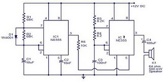
Police Sirine Circuit with IC 555