Friday, December 12, 2014
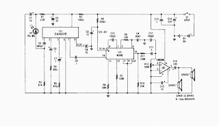
Wireless IR headphone receiver schematic

Thursday, December 11, 2014
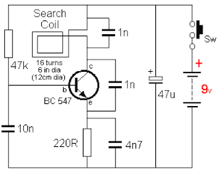
D I Y Gold Detector Schematic

Wednesday, November 19, 2014
Simple Sound to Light Converter Schematic Diagram
Figure 1 shows a simple ambit for converting an audio arresting (such as one that comes from the apostle terminals of a CD player). The ambit basically consists of a buffer/amplifier date and three clarify circuits: a high-pass filter, a mid-pass filter, and a low-pass filter. The achievement of anniversary clarify ambit drives a light-emitting diode of altered color.
The ascribe arresting is fed to the absorber date through C1. The ethics of RF and RV1 should be called so that the absorber is able to drive the three filters absorbed to its output. The low-frequency, mid-frequency, and high-frequency apparatus of the ascribe arresting are alone accustomed to canyon through the low-pass clarify (bottom filter), the mid-pass clarify (middle filter), and the high-pass clarify (topmost filter), respectively, appropriately amid them from anniversary other.
Changes in the achievement of a clarify account its agnate achievement LED to about-face on and off. In effect, agriculture a connected audio arresting to the ascribe of this ambit causes the LEDs to dance.
Thursday, November 13, 2014
Yamaha 175 Wiring Diagram and Electrical System Schematic
Yamaha 175 Wiring Color Code
| Daytime charging circuit Night time charging circuit Battery (+) circuit Ground circuit Front brake stop light Rear brake stop light Tail light Head/meter light Common circuit Headlight main circuit Headlight sub circuit Horn circuit Rectifier circuit Flasher Flasher light right Flasher light left | Green |
Tuesday, November 11, 2014
One second Audible Clock Circuit Schematic
The input impedance at pin #1 is very hight, so simply touching the pin (or a short track or piece of wire connected to it) is usually enough to provide the necessary input signal. Another way to provide an input signal consists in a piece of wire wrapped several times around any convenient mains cable or transformer. No other connection is necessary.
Circuit diagram:
Parts:
R1 = 10K
R2 = 47.K
R3 = 100R
C1 = 1nF-63V
C2 = 10µF-25V
C3 = 100nF-63V
D1 = 1N4148
D2 = 1N4148
D3 = 1N4148
D4 = LED-(Optional, any shape and color, see Notes)
D5 = 1N4148-75V 150mA Diode (Optional, see Notes)
Q1 = BC337-45V 800mA NPN Transistor
IC1 = 4024-7 stage ripple counter IC
BZ1 = Piezo sounder (incorporating 3KHz oscillator)
SPKR = 8 Ohm, 40 - 50mm diameter Loudspeaker (Optional, see Notes)
SW1 = SPST Toggle or Slide Switch (Optional, see Notes)
B1 = 3 to 12V Battery (See Notes)
Notes:
- To allow precise circuit operation in places where the mains supply frequency is rated at 60Hz, the circuit must be modified as follows: disconnect the Cathode of D1 from pin #11 of IC1 and connect it to pin #9. Add a further 1N4148 diode, connecting its Anode to R1 and the Cathode to pin #6 of IC1: thats all!
- The circuit will work fine with battery voltages in the 3 -12V range.
- The visual display, formed by D4 and R3 is optional. Please note that R3 value shown in the Parts list is suited to low battery voltages. If 9V or higher voltages are used, change its value to 1K.
- If a metronome-like click is needed, R2 and BZ1 must be omitted and substituted by the circuit shown enclosed in dashed lines, right-side of the diagram.
- Stand-by current drawing is negligible, so SW1 can be omitted.
Monday, November 3, 2014
stk392 datasheet schematic circuit diagram
 The STK392-020 is a hybrid IC for video projector
convergence correction. Since this IC integrates three
output amplifier circuits in a single package, the six
convergence correction output circuits, i.e., the vertical
and horizontal directions for each CRT of the RGB can be
formed from only two ICs.
Applications
Video projectors (both standard and high definition) test circuit
Features
•Three output amplifier circuits integrated in a single
22-pin package
•High absolute maximum supply voltage
(VCC max = ±44 V)
•Low thermal resistance (θj-c = 2.1 °C/W)
•High thermal stability (TC max = 125°C)
•Isolated early stage and output stage power supplies
•Output stage power supply switching supports high
efficiency designs.
•The input system, power supply system and output
system pins are isolated in the pin arrangement, thus
reducing the influence of the pattern layout on the
characteristics and easing design.
•Since constant current circuits are used in the pre-driver
stage, operation is stable with respect to the power
supply switching.
•The Sanyo convergence correction circuit product
lineup (the STK392-000 series) handles a wide range of
end-product classes. Therefore, the same PCB can be
used for end products from popularly-priced units to
top-of-the-line models. Package Dimensions
Monday, October 13, 2014
Latest IC Power Supply Schematic using DC DC Converter
This is an IC power supply schematic to provide +15V to all of the IC chips using two Lambda DC/DC converters. One 24V/15V DC/DC converter, Lambda PM10-24D15, will be used to provide +15V to the UC3825BN PWM IC, the IR2110 gate driver IC’s, and the ISO124 isolation IC.
Friday, September 12, 2014
PANASONIC TC L42S20B LCD TV SMPS Power Supply SCHEMATIC Circuit diagram
.jpg)


