Friday, November 14, 2014
Ultrasonic Mosquito Repeller Circuit Diagram by CD4017
Circuit Diagram:
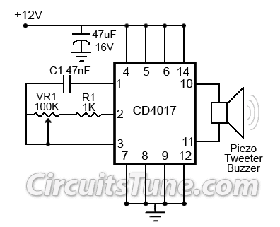 |
| Fig: Ultrasonic mosquito repeller circuit diagram |
Thursday, October 9, 2014
Switching power supply dual voltage 5v and 3 3v by LM2575 LM1117

Here is circuit Switching power supply dual voltage, output 5V 1A and 3.3V 1A.
Use IC LM2575 SIMPLE SWITCHER 1A Step-Down Voltage Regulator ,and IC LM1117 is 800mA Low-Dropout Linear Regulator. Volt suppy 9V – 60V
Detail more see to image circuit.
Wednesday, October 8, 2014
latest Temperature Controlled NICD Charger by IC LM311
This circuit is for a temperature controlled constant current battery charger. It works with NICD, NIMH, and other rechargeable cells. The circuit works on the principle that most rechargeable batteries show an increase in temperature when the cells becomes fully charged. Overcharging is one of the main causes of short cell life, hot cells pop their internal seals and vent out electrolyte. As cells dry out, they lose capacity.

Theory
The transformer, bridge rectifier, and 1000uF capacitor provide around 22 Volts of DC power to run the rest of the circuit. The 7812 regulator drops this to 12V to run the 311 comparator and 4011 nand gates.
The start switch is pressed to start the charging cycle. This causes the two 4011 nand gates, which are wired as an r-s flip-flop, to go into the charging mode. The Red LED is lit, and the VMOS FET current switch is turned on. Charging current runs though the battery pack. If the battery starts out warmer than the reference temperature, the circuit will not switch into charging mode. Let the pack cool down. When the battery pack reaches a full state of charge, the differential temperature sensor causes the flip-flop to switch off, turning off the VMOS current switch, and lighting the Green LED.
The 7805 voltage regulator is wired as a constant current regulator. This provides a safe maximum charge current for a number of different cell types. The 500 ohm resistor across the VMOS FET sets the trickle charge current which flows through the battery pack after the bulk charging is finished.
The 1N5818 diode prevents the pack from discharging if the AC power is turned off.
The resistor, diode, and capacitor around the start switch cause the circuit to auto-start when power is first applied.
The differential temperature sensor circuit works by presenting two voltages to the input of the 311 comparator. The comparator output switches on or off depending on which input is at a higher voltage than the other. As the thermistors warm up, their resistance drops, lowering the associated comparator input. Since there are two sensors, the room temperature can vary and the circuit will only react to the difference in temperature between the sensors.
Monday, September 22, 2014
300W Mosfet power amp OCL HIFI Class AB by K1530 J201
Younger student brother will take an interest to do electronics project sends a teacher. Then come to consult with me. He wants to build Mosfet power Amplifier 300W rms model the stereo Amp. Which be the character OCL the sound is good. I then try to seek the circuit gives him sees in rows the way , accidentally meet this circuit. which design by Anthony.E.Holton.
He designs this circuit well. Use power 2SK1530+2SJ201 MOSFET x 4 jigsaw puzzle parallel amounts. make have power amplify tall arrive at about 300W rms true power FULL watt. Detail other part want friends see in original circuit.
