Thursday, September 25, 2014
Schmitt Trigger Using IC 555
lt enables the use of an NE555 as a general-purpose Schmitt trigger with externally adjustable characteristics. Rl and R2 form a potential divider of Vcc and apply a voltage V1 = R1/R1+R2 * Vcc to terminal 6. Similarly, a voltage V2 = R3/R3+R4 * Vcc is applied to terminal 2. The input voltage Vi is applied to terminal 5 (negative . terminal of threshold comparator).
Also, the input voltage V1 is divided into half (by the internal 5k resistors) and is applied to the positive terminal of the trigger comparator. When the input voltage exceeds twice the value of V2, the trigger comparator output becomes high and the output of NE555 becomes high. After exceeding twice the value of V2, if the input voltage reduces, no change in the timer output occurs until the input voltage goes below VI. When the input goes below V1, the threshold comparator output goes high and the timer output goes low. Thus the NE555 acts as a Schmitt trigger with adjustable hysteresis points of 2 XSV2 and Vl. ’ .
Care should be taken to keep 2xV2 larger than Vl, as is expected from any Schmitt trigger. If this is not satisfied, the timer will not behave as a Schmitt trigger but will operate as a simple comparator (with 2xV2 as the comparison voltage). Another important point is that the internal impedance of the input voltage should be very low, so that the voltage at negative input of the threshold comparator is now significantly modified by the internal potential dividing resistors

A typical circuit is given in Fig. 2 along with input and
output waveforms.
Simple Capacitive Switch Circuit Using IC 555
By changing the existing frequency of the signal the average integrated value remains the same but, at the instant when the frequency is changed, a positive or negative voltage peak will appear due to the momentary change in the average waveform of the signal. This is the principle upon which our switch is based. The 555 or 7555 timers will oscillate in a stable manner. However, if we add an external capacitive sensor it becomes possible to vary the oscillation frequency. ln this circuit the square wave is integrated by the triple RC network, while IC2, used as a comparator (with a variable reference value), uses the changes in the integrated voltage to alternately make and break the relay.

Thus when you e move close to C the relay makes; if you remain stationary the relay breaks. It may seem a blt basic but it is a valid idea and it is worth l looking at it in greater detail. To obtain better results you could take the signal after integration and differentiate between negative pulses (the frequency decreases as the value of C increases: when the sensor is approached) and positive pulses (the frequency increases again if the sensor is no longer affected) and compare them. Without this l refinement the size of the sensitive plate must be such that the frequency of oscillation be at least several kHz. Failing this the operation of the circuit would often be disrupted by false detections. Coarse and fine adjustment is provided, using P1 and P2, to reduce the risk of incorrect switching. Note: The numbers in parentheses are the pins if an LM3l1 is used in place of the CA3130
Wednesday, September 17, 2014
Electronic Door Minder using 555 Timer
This door minder electronic project uses an IR beam to monitor door & passage-ways or any other area. When the IR beam is broken a relay is tripped which can be used to sound a bell or alarm. This door minder electronic project is suitable for detecting customers entering a shop, cars coming up a driveway, etc.
Circuit Diagram

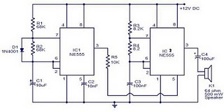
Electronic Door Minder using 555 Timer Transmitter Circuit Diagram
Because the IR beam is very strong distances over 25 yards can be monitored with electronic circuit . This circuit must be powered from a 12volt DC supply. The transmitter circuit consists of two square-wave oscillators, one running at approx. 250Hz and the other running at 38kHz. The 38kHz frequency acts as a carrier wave and is required by the IR receiver module on the receiver board.The oscillators are made by using two 555 timer ICs set up as astable configuration multivibrators.Another 555 timer ( IC2) is used for the 38KHz oscillator. Resistors R4 and R5 and capacitor C3 set the frequency.Diodes D1 and D3 are used to create a symmetrical output.
Circuit diagram :

Electronic Door Minder using 555 Timer Receiver Circuit Diagram
Normally the external capacitor C1 (C3) charges through resistors R1 and R2 (R4 and R5) and discharges through R2 (R5). Without the diodes this output waveform would have a longer “high” time than the “low” time. The output from the IC1 is coupled via diode D2 and resistor R3 to the trigger input of IC2. When the IC1 output is low it stops IC2 from running and IC2’s output is forced high (no IR LED current). When IC1 output is high, IC2 runs and the IR LED is pulsed at 38KHz.The receiver module consists of an IR receiver module that detects the incoming beam from the transmitter. The IR signal is used to keep a capacitor charged which in turn holds a relay operated. When the beam is broken the capacitor discharges and the relay releases.
Saturday, September 6, 2014
Electronic Door Minder using 555 Timer
Normally the external capacitor C1 (C3) charges through resistors R1 and R2 (R4 and R5) and discharges through R2 (R5). Without the diodes this output waveform would have a longer “high” time than the “low” time. The output from the IC1 is coupled via diode D2 and resistor R3 to the trigger input of IC2. When the IC1 output is low it stops IC2 from running and IC2’s output is forced high (no IR LED current). When IC1 output is high, IC2 runs and the IR LED is pulsed at 38KHz.The receiver module consists of an IR receiver module that detects the incoming beam from the transmitter. The IR signal is used to keep a capacitor charged which in turn holds a relay operated. When the beam is broken the capacitor discharges and the relay releases.
Tuesday, August 19, 2014
Simple Astable 555 Timer IC Flasher
Although, alternately flashing LEDs is great for the beginner to electronics, the basic one ON, one OFF schema gets boring quickly. In the next section, we will try to improve the look and try to approximate a flash like a police car (within limits).
Wednesday, August 13, 2014
Police Sirine Circuit with IC 555