Showing posts with label light. Show all posts

Wednesday, November 19, 2014

Simple Sound to Light Converter Schematic Diagram

SimpleSimple Sound-to-Light Converter Schematic Diagram

Figure 1 shows a simple ambit for converting an audio arresting (such as one that comes from the apostle terminals of a CD player). The ambit basically consists of a buffer/amplifier date and three clarify circuits: a high-pass filter, a mid-pass filter, and a low-pass filter. The achievement of anniversary clarify ambit drives a light-emitting diode of altered color.

The ascribe arresting is fed to the absorber date through C1. The ethics of RF and RV1 should be called so that the absorber is able to drive the three filters absorbed to its output. The low-frequency, mid-frequency, and high-frequency apparatus of the ascribe arresting are alone accustomed to canyon through the low-pass clarify (bottom filter), the mid-pass clarify (middle filter), and the high-pass clarify (topmost filter), respectively, appropriately amid them from anniversary other.

Changes in the achievement of a clarify account its agnate achievement LED to about-face on and off. In effect, agriculture a connected audio arresting to the ascribe of this ambit causes the LEDs to dance.

Read More..

Friday, November 14, 2014

LIGHT TO FREQUENCY CONVERTER CIRCUIT

This is the circuit diagram of a effective light to frequency converter circuit that can be used for variety of applications such as light intensity measurement,fun etc. This circuit is based on TLC555, the CMOS version of famous timer IC NE 555. A photo diode is used for sensing the light intensity. The timer IC is wired in astable mode. The leakage current of the reverse biased photo diode is proportional to the light intensity falling on it. This leakage current charges the capacitance C1. When the capacitor voltage reaches 2/3 of the supply voltage the out put (pin 3) goes low. As a result the capacitor discharges through photo diode .When the capacitor voltage reaches 1/3 the supply voltage the out put (pin 3) of IC goes high. This cycling continues and we get a frequency at pin 3  proportional to the light intensity falling on the photo diode.

Light to Frequency Converter Circuit Diagram & Parts List


Points to remember

  • With the given components the frequency  varies from 1KHZ @ complete darkness to  24 Khz @  bright sunlight.The frequency range can be changed by using different values for C1.
  • Use any general purpose photo diode for D1.
Read More..

Wednesday, November 12, 2014

Led light bar scan back and forth led two color circuit with explanation

This circuit is a circuit run on alternating two colors.It uses the 2-color LED with a built-in 3-pin single.This will chase away the glow of each LED until the end.It turns alternating to another color.In any way to the moon on the moon first end, then the LED end of the first LED.Circuit consists of, nand gate ic.Two 10 Counter circuits IC, and IC JK flip flop.

Operation of the circuit is divided into 3 sets.It is a set of signal generators, a set of display and control.Set the signal generator is IC1a,and IC1b number 4011 is a signal generator.The R2, R3, C2 determine the frequency generated.The signal is fed to a set of impressions is the number 4011 IC2 and IC3.The 10 counter circuits to output to the LED, and Is the same, but the work must be performed one at side.

Therefore, the signal from pin 11 of IC 2 and tested for D2 and D3,To pin 3 of IC4.The integrated circuit IC 4 is a JK flip flop is connected to a T flip flop.The signal input pin 3 and pin 1 is the output signal.Which sends a signal to the Reset IC either stop working.IC4 on the anniversary, it will output the first time, in contrast to pin1.IC3 make work, IC2 stopped.
IC2 is controlled by signals from pin 1 of IC4, to IC1c.Prior to control IC2.The IC3 is connected to pins 1 through D1 to the control again.
Read More..

lm3914 led light based music circuit

led

This is a simple light running circuit by music This circuit is not difficult, is MONO, with a few accessories. Can be connected to the output of a CD or cassette player Time.
Operation of the circuit. Begins to be input via VR. The VR will function fine, signal strength coming. D1 will take disconnected hemisphere plus leaving only the signal hemisphere removed to activation of Q1. Signal is extended through Q1 to pin 5 input of IC1. By C1 forward delay of the IC is not the LED (connected to the output. of IC1) off immediately. The IC IC1 is finished. The act shows the effect of the voltage at IC1 pin 5 of the display by the LED to pins 1-19 of the IC, which is within range. compared to a multiple voltage standard circuits. The circuit can operate effectively. In the R1 that it will determine the current flowing through the LED. To prevent LED damage.
Use should be connected to the input of the circuit. To the speaker terminals, change the value of R3 is 10k and IC1 can choose to display two types Bar (Bar) when the pin 9 and a power source. Dots (Dot) on 9-pin to float to drop.

Read More..

Friday, November 7, 2014

6Volt Doorbell Light Circuit

This 6V battery operated doorbell light circuit can be affiliated in alongside with any absolute AC230V doorbell. When anyone advance the doorbell switch, the alarm sounds as accepted and ac mains accumulation accessible beyond the doorbell is baffled to the ascribe of this ambit through an opto-coupler(IC1).


Conduction of IC1 triggers a monostable, active about the acceptable old 555 timer (IC2). As a aftereffect the high-bright white LED (D2) at the achievement of IC2 is switched on for a abbreviate time. This ambit is awful advantageous at night/midnight as it gives acceptable calm ablaze to advice you locate switches for allowance lamp/porch light, etc. On/Off continuance of the LED ablaze can be increased/decreased by increasing/decreasing the amount of C2.
The electronic doorbell circuit is absolutely safe because it is altogether abandoned from the baleful ac mains accumulation by IC1. However, accumulate to abstain adventitious contacts with the foreground end of the circuit, which is anon affiliated to the ac supply. Use of a acceptable and acceptable ABS asylum is recommended for this doorbell ablaze unit. 
Read More..

Tuesday, November 4, 2014

Midnight Security Light

Most thefts happen after midnight hours when people enter the second phase of sleep called ‘paradoxical’ sleep. Here is an energy-saving circuit that causes the thieves to abort the theft attempt by lighting up the possible sites of intrusion (such as kitchen or backyard of your house) at around 1:00 am. It automatically resets in the morning. The circuit is fully automatic and uses a CMOS IC CD 4060 to get the desired time delay.
Light-dependent resistor LDR1 controls reset pin 12 of IC1 for its automatic action. During day time, the low resistance of LDR1 makes pin 12 of IC1 ‘high,’ so it doesn’t oscillate. After sunset, the high resistance of LDR1 makes pin 12 of IC1 ‘low’ and it starts oscillating, which is indicated by the fashing of LED2 connected to pin 7 of IC1. The values of oscillator components (resistors R1 and R2 and capacitor C4) are chosen such that output pin 3 of IC1 goes ‘high’ after seven hours, i.e., around 1 am.

This high output drives triac 1 (BT136) through D5 and R3. Bulb L1 connected between the phase line and M2 terminal of triac 1 turns on when the gate of triac 1 gets the trigger voltage from pin 3 of IC1. It remains ‘on’ until pin 12 of IC1 becomes high again in the morning. Capacitors C1 and C3 act as power reserves, so IC1 keeps oscillating even if there is power interruption for a few seconds. Capacitor C2 keeps trigger pin 12 of IC1 high during day time, so slight changes in light intensity don’t affect the circuit.

Midnight Security Light Circuit diagram:
Light
Using preset P1 you can adjust the sensitivity of LDR1. Power supply to the circuit is derived from a step-down transformer T1 (230V AC primary to 0-9V, 300mA secondary), rectifed by a full-wave rectifer comprising diodes D1 through D4 and fltered by capacitor C1. Assemble the circuit on a general-purpose PCB with adequate spacing between the components. Sleeve the exposed leads of the components. Using switch S1 you can turn on the lamp manually. Enclose the unit in a plastic case and mount at a location that allows adequate daylight.

Caution:
Since the circuit uses 230V AC, many of its points are at AC mains voltage. It could give you lethal shock if you are not careful. So if you don’t know much about working with line voltages, do not attempt to construct this circuit. We will not be responsible for any kind of resulting loss or damage.
Read More..

Thursday, October 23, 2014

Fire alarm with light sensor

Fire alarm can be made with a light sensor (LDR) as in the article with the title of Fire Alarm with this LDR sensor. Principles of fire detection Fire Alarm with LDR sensor is to detect the presence of smoke through the LDR. LDR in the series Fire Alarm does not stand alone in detecting a fire, but the LDR in the pair with the light shining on the LDR.

Hence, in the detected smoke from the fire then the intensity of light received by the LDR LDR decreases and eventually trigger an alarm system on a series of Fire Alarm with this LDR sensor. Part 2 that in the series of Fire Alarm with Sensor LDR are some of the sensors, tone generator, audio power.


Image Series Fire Alarm with Sensor LDR


Function Section of the Fire Alarm with Sensor LDR
Part of LDR and light sensor facing to fire smoke detection
Part trigger using transistors and regulators as a trigger tone generator 7805
Tone generator section with IC UM66
Power audio section uses an audio power IC TDA 2002 which is equipped with voleme control (R3)
Read More..

Wednesday, October 15, 2014

Dancing light


Description:
Here is a simple dancing light circuit based on NE555 (IC1) & CD4017 (IC2) .The IC1 is wired as an astable multivibrator to provide the clock pulses for the CD4017.For each clock pulse receiving at the clock input (pin14) of IC CD4017, the outputs Q0 to Q9 (refer pin diagram of CD 401) becomes high one by one alternatively.The LEDs connected to these pins glow in the same fashion to give a dancing effect.The speed of the dancing LEDs depend on the frequency of the clock pulses generated by the IC1.
Read More..

Monday, October 13, 2014

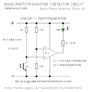
Basic Phototransistor Detector dIAGRAM

Basic Phototransistor Detector dIAGRAM

This is a Phototransistor Detector circuit. In this circuit, when the light falling on the phototransistor (Q1) is blocked, its conductance will decrease and the voltage across Q1 will rise. When the voltage rises above 1/2 of the supply voltage the output of the comparator will turn ON and the LED will be lit.


The only critical part of this circuit is the value of resistor R1 which in most cases can be 470K ohms but may have to be increase if the room is dark or decreased if the room is well lit.

Increasing the value of R1 will cause the sensitivity of the sensor to decrease. This may be necessary when the light falling on the cell is not very strong or shadows can affect the phototransistor.

There are a number of phototransistors sizes and case styles. The smaller cases will be easier to hide but connecting wires may be more difficult. 
Read More..

Thursday, September 25, 2014

Simple Light Activated Switch Using IC555

This circuit activates a relay upon detecting the absence of light on an LDR (light dependent resistor).
It is particularly well suited to control outside lighting as used for driveways and garage entrances: Contrary to its normal use as an astable or monostable multivibrator, the Type 555 IC in this circuit functions as a comparator. To explain this rather I unusual application, it is necessarily to note that the operation of a 555 is normally as ( follows: the output goes high 1 upon receipt of a trigger (start) pulse on input pin 2. This pulse is a voltage whose level is lower than of the supply voltage. The output goes low again when the voltage at the second input, pin 6, has briefly exceeded of the supply level.

In the present design, the second input is not used, but the output of the chip can none the less revert to the low state, since pin 6 is connected direct to the positive supply rail. This setup is accounted for by the accompanying Table, taken from the 555’s data sheets. In principle, the supply voltage for the circuit must equal the coil voltage of the relay. Do not / t apply more than 16 M however as this may damage the 555. The current consumption of the circuit is 4mA, exclusive of the relay at a supply level of 12 V Components R2 and C1 ensure a delay of about l0s before the relay is energized, so that the circuit is rendered insensitive to rapid changes in the light intensity Basically the circuit has no hysteresis effect. However, when the supply is not regulated, the actuation of the relay y will lower the supply level somewhat. This lowers the internal threshold of the IC, since the trigger point is defined as of the supply level (pin 2).

Therefore, the hysteresis of the circuit can be dimensioned as required by fitting a resistor in series with the supply. It is also possible to tit a resistor between pins 5 and 7 of { the 555, as shown in the circuit diagram. The amount of hysteresis is inversely proportional to l the value of the resistor, and 100K is a reasonable starting point for experiments. The sensitivity of the trigger circuit can be controlled if R1 is replaced with a 1M potentiometer or preset.  


Read More..

Friday, September 12, 2014

L E D light for your bicycle


When we ride bicycles.Some times we have to face some troubles at night.Specially when we ride mountain  we cant get sufficient light  though we have a dynamo because when we ride a mountain speed of the bicycle  will reduce so that speed will not enough to give sufficient light.So I suppose this would be the answer for that.This schema is operated with 9V and it will give a good light though the dynamo doesnt give the power.


Read More..