Showing posts with label on. Show all posts

Monday, October 13, 2014

Basic Phototransistor Detector dIAGRAM

Basic Phototransistor Detector dIAGRAM

This is a Phototransistor Detector circuit. In this circuit, when the light falling on the phototransistor (Q1) is blocked, its conductance will decrease and the voltage across Q1 will rise. When the voltage rises above 1/2 of the supply voltage the output of the comparator will turn ON and the LED will be lit.
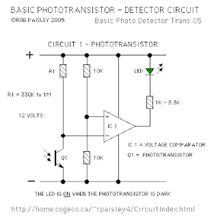


The only critical part of this circuit is the value of resistor R1 which in most cases can be 470K ohms but may have to be increase if the room is dark or decreased if the room is well lit.

Increasing the value of R1 will cause the sensitivity of the sensor to decrease. This may be necessary when the light falling on the cell is not very strong or shadows can affect the phototransistor.

There are a number of phototransistors sizes and case styles. The smaller cases will be easier to hide but connecting wires may be more difficult. 
Read More..

Wednesday, September 17, 2014

Portable Amplifier based on TEA2025

This is the diagram of simple portable amplifier schema. This amplifier schema build based on IC TEA2025 that is a monolithic integrated audio amplifier of 16-pin plastic dual in line package built by UTC manufacture. The schema has an internal thermal protection. The schema designed for portable cassette players and radios. You can also use as PC audio amplifier.

Here the amplifier diagram for stereo audio input/output:

Portable

and here the amplifier with mono audio input/output (bridge):

Portable

Stereo per channel
VCC=9V; RL=4 ohm/3W
VCC=9V; RL=8 ohm/2W

Bridge Application
VCC=9V; RL=8 ohm/5W
VCC=9V; RL=4 ohm/8W

Supply Voltage min = DC3v @ 500mA
Supply Voltage max = DC12v @ 500mA
Supply Voltage recommended = DC9v @500mA

Download TEA2025 Datasheet
Download the schematic diagram in PDF format HERE

Read More..

Monday, August 25, 2014

Timer Circuit with Independent On and OFF Delay Adjust Facility

Timer
The schema can be used for generating delays at a desired rate. The On time of the relay can be controlled by adjusting the Pot VR1 while the pot VR2 may be used to decide after how long the relay responds once the input trigger is fed by the switch S1.

 The parts list is enclosed inside the diagram.


Sourced by : Streampowers
Read More..

Friday, August 15, 2014

Laser Controlled ON OFF switch

This Laser Controlled ON/OFF switch schema is built around a 555 timer using very few components. Since the schema is very simple, even a novice can easily build it and use it as a controlling device. A laser pointer, now easily available in the market, can be used to operate this device. This schema has been tested in operational conditions from a distance of 500 meters and was found to work satisfactorily,though it can be controlled from still longer distances.
.
Laser Controlled ON/OFF switch Circuit diagram :
Laser Controlled ON-OFF Switch Circuit-Diagram
Laser Controlled ON/OFF Switch Circuit Diagram

Aiming (aligning) the laser beam exactly on to the LDR is a practical problem. The schema is very useful in switching on/off a fan at night without getting off the bed. It can also be used for controlling a variety of other devices like radio or music system. The limitation is that the schema is operational only in dark or dull lit environments.

By focusing the laser beam on LDR1 the connected gadget can be activated through the relay, whereas by focusing laser beam on LDR2 we can switch off the gadget. The timer is configured to operate in bitable mode. The laser pointers are available for less than Rs 150 in the market. The cost of the actual schema is less than Rs 50. 

Author :Dr K.P. Rao  - Copyright : EFY
Read More..

Wednesday, August 13, 2014

Battery Charger based on AVR ATMega 8535

Battery Charger in general can be interpreted as a means to recharge the battery charge. Principles of good charger circuit is capable of providing resources to perform effectively charging the battery, efficient and safe. AVR-Based Battery Charger ATMega 8535 With LCD Display This is an idea that had just emerged from the author.
In AVR-Based Battery Charger design ATMega 8535 With LCD Display is using AVR microcontroller processor charger with ATMega 8535, process the data viewer charger with LCD, a safety from a hot temperature with the temperature sensor LM35 and several buttons for setting the charger. And component power charger Battery Charger Based on AVR ATMega 8535 With LCD Display is a FET.
Click to view larger

Function-Based Battery Charger Part Series AVR ATMega 8535 With LCD Display
ATMega 8535 AVR microcontroller serves as the controlling process of the charger.
Button S1 - S5 as input data charger settings (setting the current, maximum temperature, peak voltage batteries)
LM35 Temperature Sensor function as heat sensors in the battery during charge.
LCD Display function to display data and display settings charger battery charger process measurement data.
FET serves as a power charger that will flow into the battery charging current.
Read More..