Sunday, August 10, 2014
Browse »
home»
amp
»
circuit
»
compound
»
diagram
»
driver
»
electric
»
op
»
vco
»
Electric Compound Op Amp Vco Driver Wiring diagram Schematic

Electric Compound Op Amp Vco Driver Wiring diagram Schematic
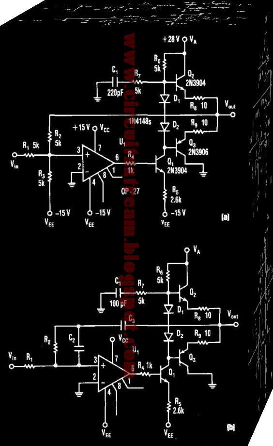
This is a simple Electric Compound Op Amp Vco Driver Circuit Diagram. This schema produces 5- to 25-V output to drive a VCO from a standard ± 15-V supply system. R7 and CI supply frequency compensation. Ql through Q3 form an inverting amplifier with a gain of two. Negative feedback through R2 closes the loop. This schema can act as a an active load-log filter and directly drive a voltage-controlled oscillator.
Electric Compound Op Amp Vco Driver Circuit Diagram

Subscribe to:
Post Comments (Atom)
No comments:
Post a Comment