Showing posts with label op. Show all posts
Showing posts with label op. Show all posts
Tuesday, October 28, 2014
Op Amp Sound Module wit IC741
This is due to the IC Acting Analog amplifiers. Mainly commonly used is the IC Op-Amp reduced. Is a valuable slew rate low. It can not know the immediate modification of the digital motion. The frequency response is not expansive adequate. Makes the sound move toward impossible with distinct and harsh. We need to arrange with an analog output amplifier with peak efficiency. And a filter wearing glut of excessive. To eliminate the sharp sound.So this circuit. must elite the IC op amp with high quality. To follow a significance LEWIS Garrett with a high and expensive. The circuit is not the numeral IC op amp to live used depending on demand.
 |
| Op-Amp Sound Module wit IC741 Circuit Diagram |
Whilst raising the power supply circuit, the power sector through candid loans isolates. Consisting of Q1, Q2, ZD1, ZD2, R5, R6, C10 and C11. The circuit Direct loans segregate the control voltage in support of supplying the integrated circuit is on 12V and-12V. The C5-C9 is a radio dish. bypass capacitor. Help indoors responding to exalted frequencies and reduce the leak of the capacitor electronic highlighting of C4 and C3. while the input to the pin 3 bedroom inverse proper IC1 to delay motion not to period improbable the. Pin 6 and the signal part is fed back through R3 and R2. which is 1.3 epoch the growth rate C1 and C2 play a part to eliminate high frequency redundant. This circuit is a circuit with the intention of extends the ordinary. The rule that the resistance of the circuit high input, to prevent the loading of the amplifier’s first album. And a low output resistance, so they can drive oodles without difficulty. The sound quality to tolerate come up to shown that is based on the IC op-amps used IC op-amp must take the elevated slew rate opamp.
Sunday, August 31, 2014
High Gain Wide Bandwidth Op Amp Wiring diagram Schematic
Ideal op-amps have infinite open-loop gain at all frequencies. This is a simple High Gain Wide Bandwidth Op-Amp Circuit Diagram. You can build a composite amplifier featuring high gain, wide bandwidth, and good dc accuracy by cascading the sections of a dual video amplifier and adding two appropriate phase-compen-sation components. The op amp drives a 150- load and provides a closed-loop gain of 40 dB.
High Gain Wide Bandwidth Op-Amp Circuit Diagram
Sunday, August 10, 2014
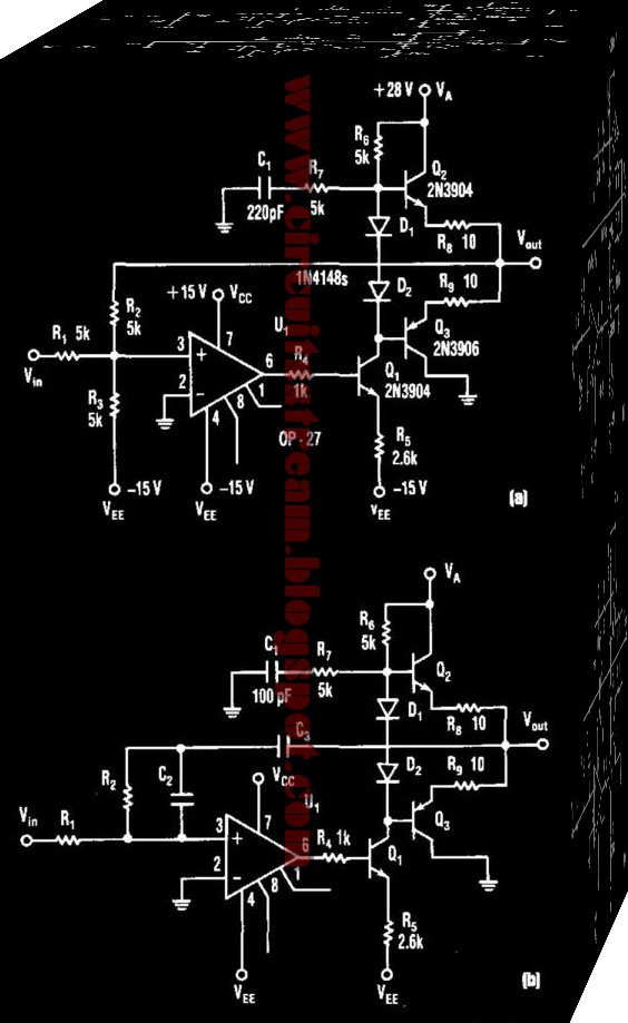
Electric Compound Op Amp Vco Driver Wiring diagram Schematic
This is a simple Electric Compound Op Amp Vco Driver Circuit Diagram. This schema produces 5- to 25-V output to drive a VCO from a standard ± 15-V supply system. R7 and CI supply frequency compensation. Ql through Q3 form an inverting amplifier with a gain of two. Negative feedback through R2 closes the loop. This schema can act as a an active load-log filter and directly drive a voltage-controlled oscillator.
Electric Compound Op Amp Vco Driver Circuit Diagram

Subscribe to:
Posts (Atom)